SURFACE

Surface network

Gathering networks built on the same wells and fluid, solved and optimised together. Draw the network, solve it with loops and reverse flow, then allocate lift gas and set chokes against the constraints at any node.

Mass balance at every node
10⁻⁹
Gas accounting with gas lift, formation to sales
10⁻⁶
Solved directly, with reverse flow allowed
Loops
CSV result tables: nodes, branches and wells
3
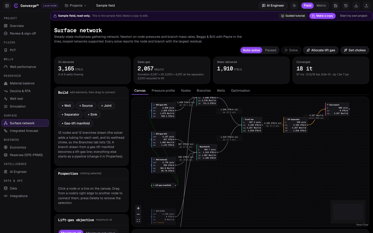
Converge surface network canvas: wells on gas lift and natural flow joining at manifolds, a trunk line to the separator and gas export, each node showing pressure and oil, gas and water rates.
The sample gathering network: six wells, two manifolds, a trunk line, the separator and gas export, solved in 18 iterations.

WHAT IT DOES

Wells, pipes and facilities in one solve

A surface network decides how much the wells can deliver once they share pipelines, manifolds and a separator. Converge solves the steady-state network by Newton-Raphson on node pressures and signed branch mass rates: mass balances at every node, one pressure equation per branch, and the oil, gas and water split balanced too.

Because branch rates are signed, looped networks and reverse flow solve without special handling. Line search, step limits and a pressure floor keep the solve robust, and when it does fail, Converge names the worst node and branch and gives the likely physical reason instead of a bare error.

Wells use their own inflow and tubing on the project fluid, so a change in the separator pressure moves every well. Gas is accounted for from formation to sales, including lift gas recycled from the separator, and the optimiser allocates lift gas by equal slope or sets chokes against the constraints you place on any node.
At a glance

  • Newton-Raphson on node pressures and branch mass rates
  • Looped networks and reverse flow
  • Beggs and Brill pipelines with the Payne corrections
  • Hilly-terrain elevation profiles
  • Gilbert, Ros, Baxendell and Achong chokes
  • Polytropic compressors to GPSA Section 13
  • Separators and sinks at fixed pressure
  • PI, Vogel, Fetkovich and back-pressure wells
  • API RP 14E erosional-velocity check
  • Gas accounting from formation to sales
  • Equal-slope lift-gas allocation
  • Rate and pressure constraints at any node

KEY CAPABILITIES

The solver, the equipment and the optimiser

Solver

A Newton solve that handles real network topologies and explains itself when it cannot converge.

  • Newton-Raphson on node pressures and signed branch mass rates
  • Mass balance at every node, one pressure equation per branch
  • Oil, gas and water split balanced at every node
  • Armijo backtracking, step caps and a 14.7 psia pressure floor
  • No reverse flow through compressors
  • Failures name the worst node and branch, with the physical reason

Pipelines

Multiphase flow along real routes, not flat lines.

  • Beggs and Brill (1973) with the revised flow-pattern map
  • Optional Payne corrections
  • Hilly-terrain elevation profiles, integrated with RK2
  • Fixed outlet temperature, or an exponential approach to ambient with a heat-transfer coefficient
  • Pressure profile along any path

Chokes, compressors and separators

The equipment between the wells and the export point.

  • Gilbert, Ros, Baxendell and Achong chokes in critical flow
  • Fixed pressure drop or fully open chokes
  • Polytropic centrifugal compressor to GPSA Section 13
  • Fixed boost, ratio or power, with multi-stage intercooling
  • Separators and sinks at fixed pressure, with gas, liquid, oil and water outlets

Wells in the network

Each well has its own inflow and tubing on the project fluid.

  • PI, Vogel composite, Fetkovich or gas back-pressure inflow
  • Beggs and Brill tubing or an imported VLP table
  • Gas lift at an injection depth
  • Wellhead choke on each well

Gas accounting and integrity

Where every standard cubic foot of gas goes, and where velocity is too high.

  • Formation, lift, arrived, recycled and sales gas, balanced
  • API RP 14E erosional velocity on every line, C = 100 by default
  • Constraints on maximum oil, gas, water or liquid rate, or minimum pressure, at any node

Optimisation

Allocate lift gas and set chokes against the constraints.

  • Equal-slope lift-gas allocation (Kanu, Mach and Brown 1981) on each well's concave hull
  • Checked against an exhaustive grid search
  • Manifold pressures fed back through the network loop
  • Optional net-value objective: oil netback less water handling and lift-gas cost
  • Rule-based choke cut-back with bisection, and shadow prices on binding constraints

WORKFLOW

From a sketch to an optimised network

  1. Draw the network

    Add wells, sources, joints, separators, sinks and a gas-lift manifold, and drag to connect them.

  2. Set the wells

    Inflow, tubing, choke and lift for each well, seeded from the project fluid.

  3. Set facilities and constraints

    Separator pressures, compressors and limits on rates or pressures at any node.

  4. Solve

    Auto-solve as you edit, or solve on demand, and read pressures and rates on the canvas.

  5. Optimise

    Allocate lift gas for maximum oil or net value, or set chokes to honour constraints.

  6. Export

    Download node, branch and well results as CSV.

VALIDATION

Balances that close exactly

Every solve is checked for conservation: mass at every node, and gas from formation to sales when gas lift is recycled through the separator.

CheckReferenceConvergeTolerance
Mass balance at every node (V29)Mass in equals mass outCloses10⁻⁹
Gas accounting with gas lift (V30)Formation plus lift gas equals gas arrived; sales gas equals formation gasCloses10⁻⁶

The network has no external comparison with another network tool yet; the benchmarks page says so. Below critical flow the choke uses a smoothing correction that the app flags as unverified.

INPUTS AND OUTPUTS

What goes in, what comes out

Inputs

  • Network topology: wells, joints, separators, sinks, compressors
  • Pipe lengths, diameters, roughness and elevation profiles
  • Well inflow, tubing, chokes and gas lift
  • Separator pressures and constraints
  • Project fluid

Outputs

  • Pressure, temperature and rates at every node and branch
  • Pressure profile along any path
  • Erosional-velocity ratio per line
  • Gas accounting from formation to sales
  • Lift-gas allocation and choke settings

Exports

  • network-nodes.csv
  • network-branches.csv
  • network-wells.csv
  • network.solve over the REST API and MCP

FAQ

Surface network: common questions

Does the network solver handle loops?

Yes. Branch rates are signed, so looped networks and reverse flow solve without special handling.

Which pipe-flow correlation does the network use?

Beggs and Brill (1973) with the revised flow-pattern map and optional Payne corrections, along hilly-terrain elevation profiles.

How is lift gas allocated?

By equal slope across each well's concave lift curve (Kanu, Mach and Brown 1981), checked against a grid search, or by net value using oil netback, water handling and lift-gas cost.

What happens when the network will not converge?

Converge names the node and branch with the largest residual and gives the likely physical reason, such as a well that cannot flow against the manifold pressure.

Has the network been benchmarked against other tools?

Not yet. Mass and gas balances close to 10⁻⁹ and 10⁻⁶, and the benchmarks page lists the external comparison as outstanding.

Solve your gathering system with your wells.